Surface Well Test Equipment

We offer integrated well testing in the exploration, appraisal and development phases of oil and gas wells. With almost 1 decades of experience coupled with state of the art equipment and technical expertise, our aim is to provide precise testing results. Clients avail our services for extended well tests, leading to early production facilities that allow them a force multiplier, further monetising their exploration wells in the shortest of time. This is executed prior to a more detailed engineering study for permanent production setups.
Our well testing tools were created and produced in compliance with global standards. All materials adhere to international quality standards such as CE/PED, ASME, API, GOST, and others. These standards are set in the United States, Middle East and Asia.

Composition of Surface Well Test Package:

SSV

SSV is a hydraulically actuated Fail – Safe gate Valve for Testing oil and gas wells with high flow rates, high pressure, or the presence of H2S. SSV is used to Quickly shut down the well choke manifold upstream in the event of overpressure, failure, a leak in downstream equipment, or any other well emergency requiring an immediate shutdown.

Technical Specification

  • Size – 3in
  • Rating – 10,000 PSI
  • Connection – 3” 1502 H/U , Flange 3 -1/16” 10M
  • Design Temperature -20 to 250 Deg F
  • Design Code – API -6A ,
  • Material – A-106 Gr B, AISI 4130
  • NACE – Yes (As per NACE MR-0175 latest Edition)
  • Application – Onshore / Offshore ,Well Production Testing / Early production System

ESD SYSTEM

ESD System is used to operate Surface safety valve (SSV) , Flow wing in flow head , which can be shut down in case of emergency with the use pilot operated ESD Button . which is looped with the air Pressure from ESD System .

Technical Specification

  • Model– Maximator /JIT/WOM
  • MAWP(Air Driven haskel pump) – 5000 PSI
  • MAWP(Hand Pump) – 5000 PSI
  • OutletPressure – 3000 PSI
  • Hydraulictank capcity – 40 ltr
  • Noof Hydraulic output – 3 nos
  • Material(body) – SS304
  • MaterialFitting – SS 316
  • RemoteESD Station – 3nos
  • Reliedvalve Set Pressure – 3500 PSI
  • PilotAir Pressure – 30-40 PSI
  • Connection– ½” NPT
  • Airpressure – 100PSI

3” Flexible flow line (Coflexip hose)

Coflexip hoses have many advantages over conventional pipework in that they can come in longer sections, give better resistance to corrosion and low restrictions to fluids passing through them, e.g. no elbows in-line, they also offer a wider range of physical and mechanical characteristics.

Technical Specification

  • Rating– 10,000 PSI
  • Length– 45 Feet
  • Connection– 3”  1502 Fitting ,
  • TestPressure – 15,000 PSI
  • Liner Details


High Pressure & Low Pressure Piping

High and Low pressure iron are used to connect different Surface Equipment for Testing the oil and gas wells. Which comes with quick connection – hammer union.

Technical Specification for High pressure Piping

  • Size– 3in
  • Rating– 10,000 PSI & 5000 PSI
  • Length– as per Requirement
  • Connection– 3”  1502 H/U & 3” 602 H/U
  • DesignTemperature -20 to 250 Deg F
  • DesignCode – ASME 3
  • Material– A-106 Gr B, AISI 4130
  • NACE– Yes

Technical Specification for Low pressure Piping

  • Size– 3in , 4” , 6”
  • Rating– 1000 PSI Rated
  • Length– as per Requirement
  • Connection–  3” 202 H/U
  • DesignTemperature -20 to 250 Deg F
  • DesignCode – ASME 3
  • Material– A-106 Gr B, AISI 4130
  • NACE– Yes

Data header

Data header is located directly upstream of the choke manifold and downstream of the surface safety valve (SSV) and provides access to the flow stream for pressure and temperature data acquisition, produced fluid sampling, and chemical injection.

Technical Specification for High pressure Piping

  • Size– 3in
  • Rating– 10,000 PSI & 5000 PSI
  • Length– as per Requirement
  • Connection– 3”  1502 H/U & 3” 602 H/U
  • DesignTemperature -20 to 250 Deg F
  • DesignCode – ASME 3
  • Material– A-106 Gr B, AISI 4130
  • NACE– Yes

Technical Specification for Low pressure Piping

  • Size– 3in , 4” , 6”
  • Rating– 1000 PSI Rated
  • Length– as per Requirement
  • Connection–  3” 202 H/U
  • DesignTemperature -20 to 250 Deg F
  • DesignCode – ASME 3
  • Material– A-106 Gr B, AISI 4130
  • NACE– Yes

Choke Manifold

The choke manifold is used to control the fluid from the well by reducing the flowing pressure and by achieving a constant flow rate before the fluid enters the processing equipment on the surface.

Technical Specification

  • Size– 3in
  • Rating– 15,000 PSI
  • Qty– 1 Nos
  • Connection– 3”  1502 H/U
  • DesignTemperature -20 to 320 Deg F ( PX)
  • DesignCode – API 6A , PSL -3
  • Material –AISI4130
  • NACE– Yes ( NACE Mr-0175)
  • Valve– 3 1/16” Gate valve PSL -3
  • PerformanceRequirement –
  • DesignStandard – API6A-21th , NACE MR-0175
  • SkidDesign- as per DNV 7.1 & 2.7.3
  • AllRing groove- Inconel 62
  • Adjustable Choke– 1/8” to 2” , Manually adjustable valve
  • Tungstencarbide
  • Manually Adjustable typevalve
  • PositiveChoke Beans – Full Set Choke Beans
  • 2/64”increments up to 64/64’’and
  • 8/64’’incrementsupto 128/64’’
  • ChokeBeans are fully lined with TC insert

Air Compressor

High flow rate air compressor specially designed with crash frame structure, suitable for Offshore applications will be equipped with suitable lifting slings and standard eye pads to ensure safe lifting at offshore conditions.

Capacity

  • 450CFM @120 PSI
  • Powerdriven Flame Proof Motor

Application

  • Onshoreoperation
  • Well/ProductionTesting
  • EarlyProduction

Oil Manifold

Oil and gas manifold is to divert the flow of oil and gas from separator or surge tank to other burner or gas flare or to other flowline.

Technical Description

  • PressureRating – 1440 PSI
  • TestPressure – 2160 PSI
  • TemperatureRating – ( -20 t0 212 Deg F)
  • Noof valve – 5 Nos
  • FlangeClass – 600#
  • Service:Sour , NACE MR-0175 D
  • Connection
    • Oilinlet – 3” 602
  • Applicablecode – ASME 3 , NACE Mr-0175

Gas Manifold

Gas from the separator flows through the gas manifold which connected to the separator gas line and is directed to one of two gas flares Gas manifold is equipped with 2 ball valves.

Technical Description

  • PressureRating – 1440 PSI
  • TestPressure – 2160 PSI
  • TemperatureRating – ( -20 t0 212 Deg F)
  • Noof valve – 5 Nos
  • FlangeClass – 600#
  • Service:Sour , NACE MR-0175 D
  • Connection
    • Oilinlet – 3” 602
  • Applicablecode – ASME 3 , NACE Mr-0175
  •  Connection
    • InletConnection – 3in 602 Th
    • OilOutlet connection – 3in 602 W
    • GasOutlet Connection – 4”
    • WaterOutlet connection – 2in


  • UStamped – yes
  • Shrinkage Tester , Sampling point , Air Scrubber – yes
  • Skid Mounted – yes
  • Slings– Yes
  • NACE – yes (NACE MR-0175)

Three Phase Separator

The 3-phase separator is an instrumented vessel that separates well effluent into three phases—oil, gas, and water—for well testing. The Separator Consist of the Vessel m oil and water flow meter system , for gas measurement have Senior orifice .

Technical Specification

  • Phase-3 Phase
  • Orientation– Horizontal
  • FlowHandling Capacity
    • GasFlow – 5 to 60 MMSCFD ( 2in & 6in orifice )
    • LiquidFlow Rate –16000 BPD
  • TestPressure – 2150 PSI
  • Retention time– 1 Min
  •  Liquid Meter Range
    • OilMeter Range – 50 –

    13000 BPD

    • WaterMeter Range – 50 –

    13000 BPD

    Design Code – ASME Sec VIII Div-1 , API 12J , ASME B31.3

Surge Tank

The Surge tank is a Pressurized vessel is used to measure the liquid flow rate and obtain an accurate measurement of shrinkage and the meter factor.

Technical Specification

  • Capacity– 100 BBL ( Dual Compartment)
  • Surgetank operating Pressure – 150 PSI
  • DesignTemperature – ( -20 Deg to 212 Deg F)
  • Service– H2s
  • Service– H2s ( As per NACE MR- 0175 Latest Edition )
  • Bypass Manifold – Yes
  • Level indicator – Level Sensor /Sight Glass with Drain
  • SkidDesign – As per DNV 7.1
  • VesselDesign – As per ASME Div-1
  • PressureSafety valve – Yes ( 2nos)
  • GroundingDevice – yes

Vertical Flare Stack

Vertical Flare System is skid mounted, and is used for continuous flaring of produced gas.

Technical Specification

Flare Type Mobile flare, guy rope supported

Type of operationIntermittent

Supply header size – 6 Inches

Total height including tip – 12 M/ 40 Ft

Noise level – 75 dBA

Pilot Gas – LPG

Service – H2S

Total pilot gas consumption rate for 1 Pilot (Min. / Max.) – 2 / 3 Nm^3/hr

Power supply required for instruments -1Ph 230V 60Hz

Pilot Flare – Hi-Tech Combustion

Test Pressure – 300 PSI

Inlet Connection – 3” 602 T

Skid – As Per DNV 2.7.1

Dimension (L X W X H) – 2.01 X 2.01 X 9.14 (mtr)

WEIGHT – 1500 Kg

Gauge Tank

The atmospheric gauge tank, a no pressurized vessel, is used to measure low flow rates or to calibrate metering devices on the separator oil lines in a testing system. When the flow rate is too low to efficiently drive oil to the burners, the tanks can also be used for temporarily storing the oil.


These skid-mounted units have two compartments. As a transfer pump empties one compartment, the other is being filled. A sight-glass level built into each tank is used to calculate the change in volume based on the physical dimensions of the tank.

Technical Specification

  • Capacity– 100 BBL ( Dual Compartment)
  • WorkingPressure – Atmospheric
  • Bypass Manifold – Yes
  • Level indicator – Level Sensorwith  Alarm in both compartment / Sight Glass with Drain
  • Manhole – yes (For Inspection)
  • SkidDesign – As per DNV 7.1
  • GroundingDevice – Yes
  • Gasoutlet or vent – 6” with Flame Arrestor

Storage Tank

The atmospheric Storage tank, a no pressurized vessel, is used to Store the Crude oil and Water . Storage tank Design to measure low flow rate or calibrate metering devices on the separator oil lines in a testing System. When the flow rate is too low to efficiently drive oil to the burners, the tanks can also be used for temporarily storing the oil.

Technical Specification

  • Capacity– 200 BBL (Single Compartment)
  • Qty– 2nos (Total 400 BBL)
  • WorkingPressure – Atmospheric
  • Level indicator – Level Sensor with Alarm in both

  • compartment/ Sight Glass with Drain
  • Manhole – yes (For Inspection)
  • SkidDesign – As per DNV 7.1
  • GroundingDevice – Yes
  • Gasoutlet or vent – 6” with Flame Arrestor

Oil Transfer Pump

The transfer pump is used to pump oil from a tank to a burner or from a tank to an available loading bay or flow line header.

Technical Specification

  • Make– Mission Magnum / KSB/ UT/Roto
  • Pumptype – Centrifugal pump
  •  Connection
    • Suction– 3in 602 H/U
    • Discharge– 3 in 602 H/U
  • FlowCapacity – 5000 BPD
  • TemperatureRating – 60 Deg C
  • MOC- H2sRated ( Wet Part)
  • MOC – SS 316 L , Cast iron – Body
  • Working Pressure – 150 PSI
  • Area Classification- Zone-II,Flame proof
  • Starter– DOL
  • Skid Design – As per DNV 7.1
  • Grounding Device – Yes
  • Design Standard – ASME B31.3, DGMS , NACE MR-0175 , API Pu

  • Data measurement – As per Client Requirement
    • Pressure,temperature, level transducers
    • Cabling
    • Computer hardware and software
    • Pressure gauges, 0‐5000psi, 0‐2000psi, 0‐1000 psi, 0‐500 psi, 0‐100 psi
    • Thermometers,dial type
    • Gas gravity meter
    • Centrifuge(manual)
    • Hydrometerset
    • Ultrasonicwall thickness tester
    • Portablenatural gas, CO2 and H2S detection equipment
    • Deadweighttester
    • Resistometer
  • Designcode –Class -I , Division II Rated Cabin

Lab Cabin and DAQ Lab

DAQ -Lab Cabin is generally used to collet Data from different measurement points in the surface well testing spread , Lab Cabin is air conditioned equipped with all explosion proof switches electrical system inside the cabin , Smoke Detector are installed in case of file emergency , Emergency and escape hatch , all the cabin items which is required to measure or gather the field data , such as gas gravitometer , hydrometer , visco meter etc.

Technical Description

  • DAQSystem – Wired
  • DAQSoftware – Fekete or Equivalent
  • DAQComputation – As per Industry guidelines
  • Data recording – online
  • Electronicsitem – Weather proof , Flame proof
  • GasAlarm / Shut down System
  • Emergency EscapHatch
  • Air Purged on Start-up

Indirect Water Bath Heater

The Indirect Water Bath Heater (I.W.B.H) is a designed skid mounted Used for in direct crude oil heating , Indirect brine heating and Indirect water heating The complete vessel is insulated so no heat loss and increases its reliability & capacity to heat effluent more efficiently

Technical Specification

  • Heating capacity – 3-3.5 MMBTU

  • Dimension (shell) – 1830 O.D x 3200 L mm

  • Shell Pressure Rating – Atmospheric

  • Gas Inlet – 1” NPT FEMALE

  • Operating pressure (coil) – 5000 PSI

  • Test pressure (coil) – 7500 PSI

  • Temperature (coil) –  -20 to 350 DEG F

  • Manifold – 3-1/8 “ 5K PSI

  • Service  – H2S

  • Standards – NACE MR 01 75/API 12K/ API 6K

  • Dimension – 6012 x 2450 x 2864 mm

  • Water level indicator – Level sensor / Sight glass

  • Shell capacity   – 15 BBL

  • Operating power supply  – 4- phase , 440 V AC
  • Connection cable – 4-coíe double aímoíed DGMS Approved.

  • Diesel level indicator  – Level sensor/ Sight glass

  • Temperature (vessel) – R.T.D Sensor / analog gauge

  • Temperature (Inlet/Outlet) – Analog gauge

  • Insulation – Insulated

  • Insulation Thickness – 75 MM

  • Chimney Height – 4 meter

  • Skid – As Per DNV 2.7.1

Generators & Lights

Technical Specification

  • capacity – 62.5 & 125 Kva

  • Phase – 3 Phase

  • Make – Ashok Leyland/Kirloskar

  • Emergency switch – AVAILABLE

  • Intensity – 120 W LED= 400 W MH/HPSV Lamp

  • Lights – LED Flameproof

  • Light Pole Base – Light Pole Base 3/5 no

  • Weight (Light pole base) – 400 Kg

  • Dimension (L X W X H) 62.5 Kva – 1.93 X 1.07 X 1.22 (mtr)

  • Dimension (L X W X H) 125 kva – 2.82 X 1.35 X 1.83 (mtr)

  • Dimension – 6012 x 2450 x 2864 mm

  • Weight (kg) 62.5 Kva  – 1500 Kg

  • Weight (kg) 125 Kva – 2600 Kg

Atmospheric gauge tank

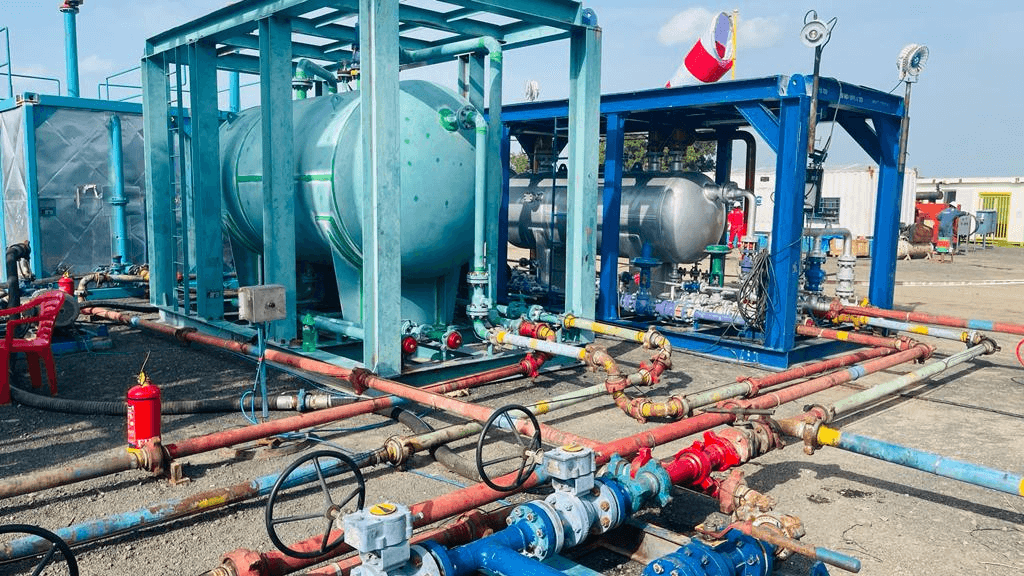
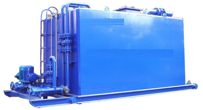
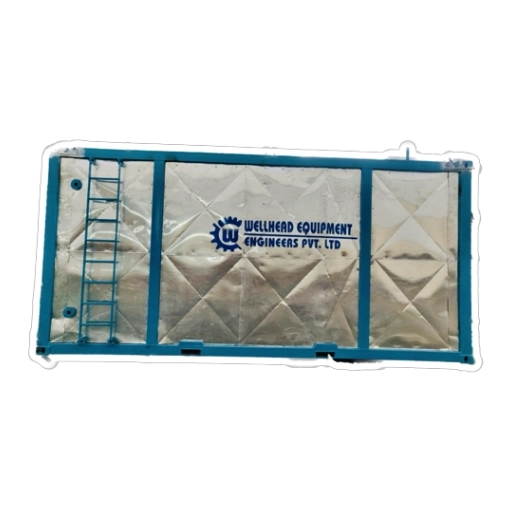
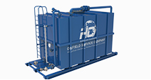
Atmospheric gauge tankis used for the storage of produced fluids, calibration of the metering instruments on the test separator and helps oil effectively drive to the burner boom.

Choke Manifold

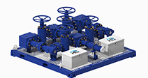
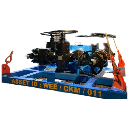
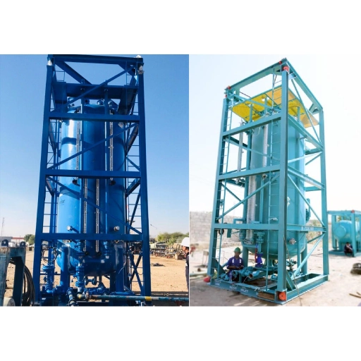
Choke Manifold is an assembly which consist of high-pressure valves and chokes, used for reducing the pressure from the well head. It is operated by opening and closing an adjustable or fixed choke.

Burner boom

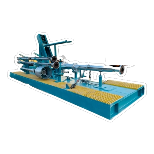
Burner boom is assembly used for the disposal of the produced fluids during the operation. Burner assembly has combustion water injection system for proper burning and operation.

Surface Safety Valve (SSV)

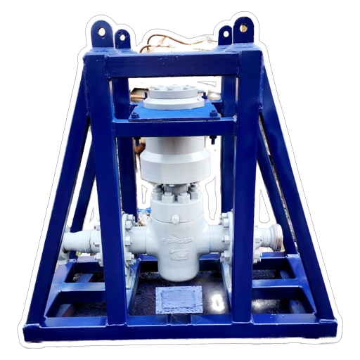
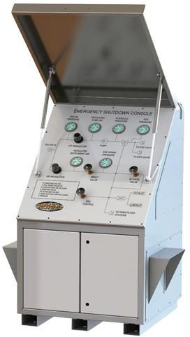
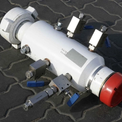
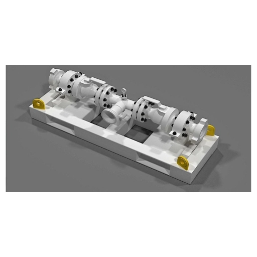
Surface Safety Valve (SSV) is one of the imp ortant safety equipment of the well testing operations with high flow rate and high pressure. Controlled by ESD system, SSV automatically shuts down the flow and prevent injury of personnel and damage of the facility.

Diverter manifoldis

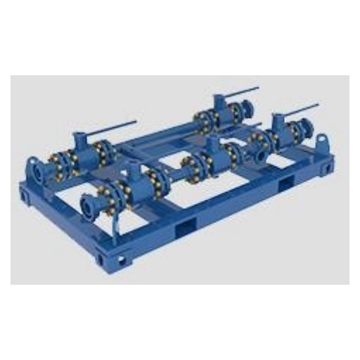
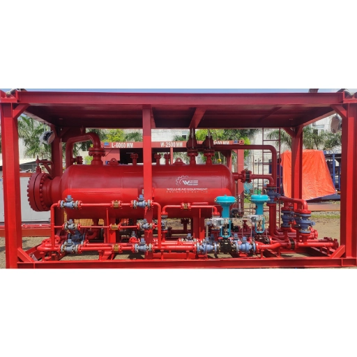
Diverter manifoldis valve assembly, used for diverting the produced oil and gas to the proper process destination. Oil diverter manifold diverts oil to the burner boom or surge tank, while gas diverter manifold diverts to flare stack or burner boom.

Transfer pumps

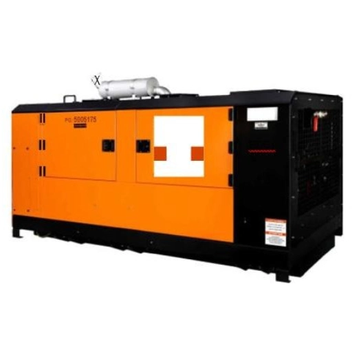
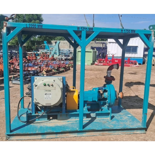
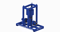
Transfer pumps used for filling and emptying the tanks and increasing the pressure for burner boom. Pumping unit is equipped with explosion proof electrical motor and control panel. The common type of pump is centrifugal, while gear and screw types are also available depending on the operation conditions.